
Network topology defines how devices connect, communicate, and fail within your infrastructure. Get it wrong, and you pay for it in latency, outages, and wasted bandwidth. Yet many IT professionals still treat topology as a documentation exercise rather than a performance decision. This guide covers the full spectrum of network topology types, from foundational concepts to the spine-leaf designs powering modern data centers, with enough technical depth to inform real infrastructure decisions. Whether you are auditing a legacy three-tier setup or designing a new fabric, this is where to start.
Table of Contents
- Key takeaways
- Network topology fundamentals: physical vs. logical
- From three-tier to spine-leaf: the architecture shift
- Spine-leaf design principles: the technical details
- OSPF in topology design: scaling and SPF considerations
- Network topology visualization and software tools
- My take on topology as a strategic discipline
- See your topology clearly with Netverge
- FAQ
Key takeaways
| Point | Details |
|---|---|
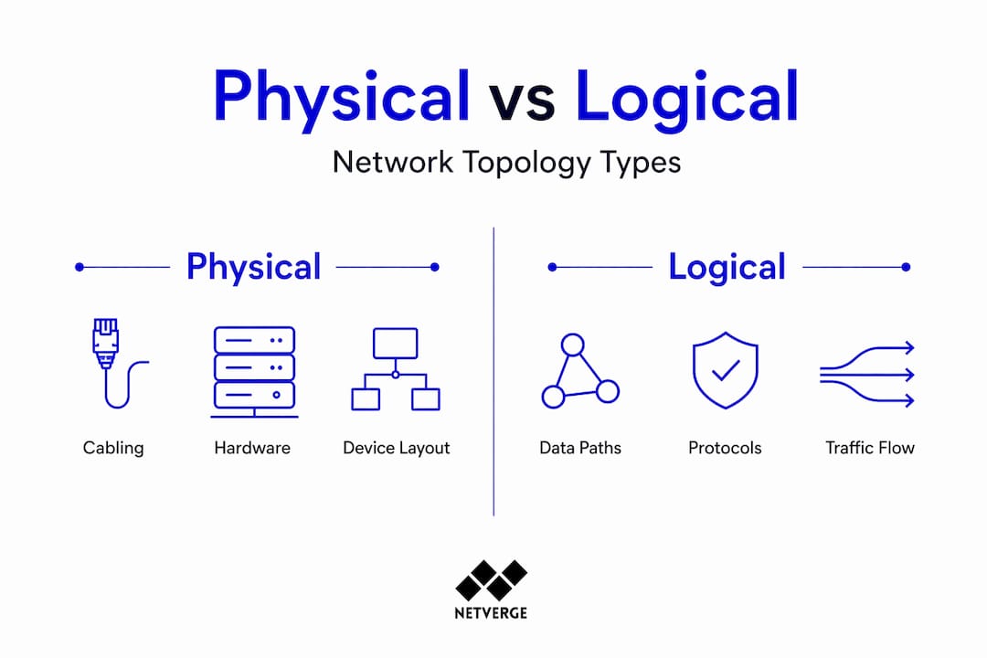
| Physical vs. logical topology | Both layers must align. Physical layout determines cabling; logical topology determines how data actually flows. |
| Spine-leaf is the data center standard | Spine-leaf delivers predictable two-hop latency and full bandwidth utilization, replacing three-tier designs for East-West traffic. |
| STP is a liability in modern networks | Classic STP blocks redundant links and converges slowly. Spine-leaf eliminates STP dependency through Layer 3 routing. |
| OSPF area design matters at scale | Poorly sized OSPF areas cause SPF recalculation storms. Limit area size and summarize routes to protect CPU headroom. |
| Visualization drives operational clarity | Topology diagrams are not just documentation. They are live operational tools when integrated with real-time monitoring platforms. |
Network topology fundamentals: physical vs. logical
Network topology is the structural arrangement of nodes and links in a computer network, and it splits into two distinct categories. Physical topology describes the actual hardware layout: how cables run, where switches sit, and what connects to what in the real world. Logical topology describes how data flows through that infrastructure, which can differ significantly from the physical layout.
The seven major topology types you will encounter in practice are Point-to-Point, Bus, Ring, Star, Tree, Mesh, and Hybrid. Here is how they compare across the dimensions that matter most for infrastructure decisions:
| Topology | Fault tolerance | Scalability | Typical use case |
|---|---|---|---|
| Point-to-Point | Low | None | WAN links, dedicated leased lines |
| Bus | Very low | Limited | Legacy LANs, small offices |
| Ring | Moderate | Limited | Legacy token ring, some MAN designs |
| Star | Moderate | Good | Enterprise LANs, branch offices |
| Tree | Moderate | Good | Hierarchical campus networks |
| Mesh | High | High | Core networks, critical infrastructure |
| Hybrid | Varies | High | Data centers, large enterprise |
Star topology remains the most common for enterprise LANs because it isolates failures to individual nodes. A single failed cable or NIC does not take down the rest of the segment. Mesh topology, by contrast, provides maximum redundancy at the cost of cabling complexity and port consumption. Full mesh becomes impractical beyond a handful of nodes, which is why partial mesh is more common in practice.

Hybrid topologies combine elements of multiple types and represent the reality of most production networks. Your data center fabric might run a mesh core with star-connected access layers, all documented in a computer network diagram that maps both physical and logical relationships.
Pro Tip: When selecting a topology type, start with your failure domain requirements. High-availability workloads need redundant paths. Cost-sensitive branch offices can tolerate star topology with a single uplink. Matching topology to actual risk tolerance prevents over-engineering and under-engineering simultaneously.
From three-tier to spine-leaf: the architecture shift
The traditional three-tier model served enterprise networks well for decades. It stacks three layers: core switches at the top handling inter-VLAN routing, aggregation switches in the middle connecting access layer to core, and access switches at the bottom connecting endpoints. The design is logical and hierarchical. It also has serious structural problems when applied to modern data center workloads.
The core issue is traffic pattern mismatch. Over 80% of data center traffic is now East-West, meaning server-to-server communication within the same data center. Three-tier architecture was built for North-South traffic: clients talking to servers. When East-West traffic dominates, packets must travel up through aggregation and core layers just to reach a server on the same row. That adds unnecessary hops and latency.
STP compounds the problem. Classic STP takes 30 to 50 seconds to converge after a topology change. Even RSTP, which converges in 1 to 5 seconds, introduces unpredictability during failover events. Beyond convergence speed, STP blocks redundant links to prevent loops, which means a 40 Gbps uplink sitting idle while the active link carries all traffic. That is 50% of your bandwidth wasted by design.
Spine-leaf architecture resolves both problems. It is a two-tier Clos topology where every leaf switch connects to every spine switch, and no other connections exist. The result is a bipartite graph that delivers consistent, predictable performance across the fabric.
Key advantages of spine-leaf over three-tier:
- Every leaf is exactly two hops from any other leaf, regardless of fabric size
- Layer 3 ECMP achieves near 100% bandwidth utilization compared to roughly 50% under STP
- No STP dependency eliminates blocking and slow convergence
- Horizontal scaling adds leaf switches without redesigning the fabric
- Failure domains shrink because no single spine or leaf is a single point of failure
Pro Tip: Before committing to a topology redesign, map your actual traffic flows. If your monitoring data shows predominantly East-West patterns, spine-leaf is the right call. If North-South still dominates, a well-tuned three-tier may serve you adequately without the migration cost.
Spine-leaf design principles: the technical details
The strict cabling rule in spine-leaf is non-negotiable. Leaf switches connect only to spine switches. Spine switches connect only to leaf switches. No leaf-to-leaf links. No spine-to-spine links. This bipartite graph structure is what guarantees the non-blocking, predictable behavior the architecture promises.
Here is how a well-designed spine-leaf fabric operates at the technical level:
- Layer 3 routing at the leaf. Each leaf switch runs Layer 3 routing, terminating VLANs locally and advertising prefixes to the spines. This eliminates the need for STP across the fabric.
- ECMP load balancing. Equal-Cost Multi-Path routing distributes traffic across all available spine uplinks simultaneously. Every uplink is active, every cycle.
- Two-hop latency guarantee. Any server on any leaf reaches any other server on any other leaf in exactly two hops. This uniform latency is critical for latency-sensitive workloads like distributed databases and real-time analytics.
- VXLAN with BGP EVPN. VXLAN overlays with BGP EVPN extend Layer 2 adjacency across the Layer 3 fabric, solving VM mobility and multi-tenant isolation without collapsing back to a flat Layer 2 domain.
- Oversubscription planning. A 3:1 oversubscription ratio is common for general-purpose workloads. High-performance computing or storage clusters may require 1:1. Get this wrong and you create congestion at the leaf uplinks under peak load.
- Spine port count limits scale. The number of ports on your spine switches determines how many leaf switches you can add. Plan your spine hardware with headroom for growth, because adding spines later requires re-cabling every leaf.
| Design parameter | Recommended value | Impact if misconfigured |
|---|---|---|
| Oversubscription ratio | 3:1 general, 1:1 HPC | Congestion, throughput degradation |
| Spine uplinks per leaf | All spines | Asymmetric load, reduced redundancy |
| ECMP paths | Equal cost to all spines | Uneven traffic distribution |
| VXLAN VNI planning | Pre-allocated ranges | Tenant isolation failures |
Pro Tip: Deploy a network topology visualization tool from day one of your spine-leaf build. Documenting the physical and logical layers as you go prevents the operational debt of trying to reverse-engineer a fabric after it is in production. Integrate that documentation with your monitoring platform for live correlation.
OSPF in topology design: scaling and SPF considerations
OSPF remains a common underlay protocol in spine-leaf fabrics and legacy campus networks alike. Understanding how it interacts with your topology is not optional. It is where many architects introduce instability without realizing it.
OSPF is a link-state protocol. Every router in an area floods Link-State Advertisements to build a complete topology map, then runs the SPF (Shortest Path First) algorithm to compute optimal routes. The SPF algorithm is CPU intensive, and every topology change triggers a recalculation. In a stable network, this is manageable. In a flapping network, SPF recalculations can spike CPU utilization and destabilize routing across the area.
Key design practices to control OSPF behavior at scale:
- Limit area size. Limiting area size and summarizing routes prevents excessive SPF recalculations that burden CPU. A common guideline is no more than 50 to 100 routers per area.
- Use area summarization. Route summarization at area boundaries reduces the LSDB size in the backbone area and limits the blast radius of topology changes.
- Tune SPF timers. Incremental SPF and SPF delay timers let you control how aggressively the algorithm reacts to changes. Backing off SPF timers prevents cascading recalculations during link flaps.
- Configure DR/BDR elections carefully. On multi-access segments, DR and BDR elections reduce adjacency complexity. Assign priority explicitly rather than relying on defaults.
- Stabilize physical links first. No amount of OSPF tuning compensates for a flapping physical interface. Address hardware and cabling issues before adjusting protocol timers.
For large-scale spine-leaf fabrics, RFC 7938 recommends eBGP as the underlay protocol over OSPF, primarily because BGP scales better and provides more granular policy control. OSPF still makes sense for smaller fabrics and campus underlays where its operational simplicity outweighs BGP's complexity.
Pro Tip: Tune OSPF SPF delay and hold timers before you need to. In a large fabric, a misconfigured timer under a link-flap event can cause a routing storm that takes minutes to stabilize. Set incremental SPF, configure BFD for fast failure detection, and test failover behavior in a lab before production deployment.
Network topology visualization and software tools
A network topology diagram is not just a picture for the documentation folder. It is an operational tool. When a link goes down at 2 a.m., the engineer responding needs to know immediately what is affected, what the redundant paths are, and where to look first. A current, accurate topology diagram cuts that response time significantly.
Topology visualization software falls into two categories. Static diagramming tools like draw.io or Microsoft Visio let you manually build physical and logical diagrams. They are accurate when you create them and drift from reality the moment someone changes a cable without updating the diagram. Dynamic topology tools auto-discover devices, map connections in real time, and update the diagram as the network changes. The operational value difference between these two categories is significant.
| Software category | Auto-discovery | Real-time updates | Monitoring integration | Best for |
|---|---|---|---|---|
| Static diagramming | No | No | No | Documentation, planning |
| Network management platforms | Yes | Yes | Yes | Operations, troubleshooting |
| AI-powered observability | Yes | Yes | Deep correlation | Complex, multi-site fabrics |
The integration between topology diagrams and monitoring is where real operational value emerges. When an alert fires, a platform that can overlay that alert onto a live topology map gives you immediate context. You see not just that a link is down, but exactly where it sits in the fabric, what it connects, and what traffic paths are affected.
Pro Tip: Maintain both physical and logical topology diagrams. Physical diagrams show cabling and hardware. Logical diagrams show VLANs, routing domains, and overlay networks. They answer different questions during an incident. Keeping both current is the discipline that separates well-run networks from reactive ones.
My take on topology as a strategic discipline
I have spent years watching organizations treat network topology as something you design once and then forget. The diagram goes into a shared drive, the network grows organically, and six months later nobody can tell you with confidence what the actual topology looks like. That is not a documentation problem. It is a strategic failure.
What I have learned is that the architects who get the most out of spine-leaf are not the ones who read the most white papers. They are the ones who treat topology as a living model of their infrastructure. They instrument it, visualize it continuously, and make design decisions based on observed traffic patterns rather than assumptions.
The OSPF and STP mistakes I see most often are not configuration errors. They are design errors made because the architect did not understand how the protocol interacts with the topology at scale. STP on a three-tier network with 200 switches is not just slow. It is a latent failure waiting for the wrong link to flap. Most teams do not discover this until it happens in production.
My honest take on AI-driven monitoring: it changes what topology means operationally. When your platform can correlate a BGP session drop with a physical interface event and automatically trace the impact across the fabric, topology stops being a static diagram and becomes a dynamic model you query in real time. That is the direction every serious network team should be moving toward.
— Jim
See your topology clearly with Netverge
Understanding topology types is the foundation. Operating them with confidence requires visibility at every layer of your infrastructure.
Netverge delivers AI-powered network monitoring that maps your physical and logical topology in real time, correlates alerts to specific fabric locations, and surfaces anomalies before they become outages. Whether you are managing a spine-leaf data center fabric, a multi-site enterprise WAN, or a complex MSP customer portfolio, Netverge gives you the operational clarity to act fast and accurately. MSP teams get topology-aware monitoring across all customer environments in a single interface. Vergepoints hardware extends physical visibility to every location without complex agent deployments. Start with a free trial and see your network the way it actually is.
FAQ
What is network topology?
Network topology is the structural arrangement of nodes and links in a computer network, covering both physical layout (hardware placement and cabling) and logical layout (how data flows between devices). The seven major types include star, mesh, ring, bus, tree, point-to-point, and hybrid.
What is spine-leaf topology and why does it matter?
Spine-leaf is a two-tier data center architecture where every leaf switch connects to every spine switch, guaranteeing two-hop latency between any two endpoints. It replaces three-tier designs by using Layer 3 ECMP to achieve near 100% bandwidth utilization and eliminating STP-related blocking and slow convergence.
How does OSPF affect network topology design?
OSPF builds a complete topology map using link-state advertisements and computes routes with the SPF algorithm, which is CPU intensive. Poorly sized OSPF areas or unstable links trigger frequent SPF recalculations that can destabilize routing. Limiting area size, summarizing routes, and tuning SPF timers are the primary mitigations.
What is the difference between physical and logical network topology?
Physical topology describes the actual hardware layout, including device placement and cable runs. Logical topology describes how data flows through that infrastructure, which can differ from the physical layout. Both layers must be documented and understood for accurate troubleshooting and design decisions.
What network topology software should IT teams use?
Dynamic topology tools with auto-discovery and real-time updates provide significantly more operational value than static diagramming tools. Platforms that integrate topology visualization with network monitoring and alerting, such as AI-powered observability platforms, give teams the fastest path from alert to resolution during incidents.