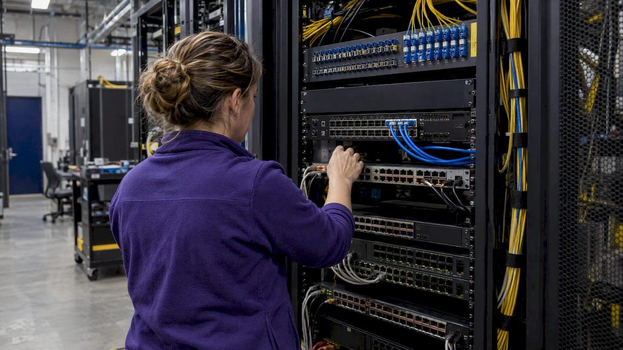
Instrument traffic-convergence points and internal segment boundaries first, and favor TAPs over SPAN ports on any high-volume or security-critical link. From there, packet brokers and BPF filtering handle duplicate traffic and load. The sections below walk through mapping observation points, choosing TAP versus SPAN, sizing for capacity, and handling OT constraints so your sensor deployment closes gaps instead of creating new ones.
TL;DR:
- Deploy TAPs on security-critical and high-utilization links to ensure reliable traffic capture, while reserving SPAN ports for low-traffic or troubleshooting segments.
- Place sensors at traffic convergence points like core switches, data center interconnects, and internet gateways to maximize visibility coverage with fewer devices.
- Use BPF filters, sampling, and deduplication strategies to manage duplicate packets and ensure sensors can handle link speeds without dropping data.
- Continuously review and update sensor placement whenever network topology or traffic patterns change to maintain effective monitoring coverage.
- For industrial environments, use passive, protocol-aware sensors at process network points, avoiding inline deployment to prevent control system disruptions.
Table of Contents
- Observation points and traffic-convergence zones: where to place sensors first
- TAP vs SPAN and where to put a packet broker
- Handling duplicates, sampling, and capacity: BPF, sampling rates, and dedupe strategies
- Multi-sensor deployment patterns and coverage optimization
- East-west visibility and segment boundary monitoring
- OT and ICS placement rules: passive, protocol-aware monitoring
- Deployment checklist: pre-deploy mapping, installation steps, and common pitfalls
- Integration with existing network management and security systems
- Impact of network topology changes on sensor placement
- Best practices for sensor placement in cloud and virtualized environments
- Security considerations for sensor deployment locations
- Legal and privacy implications of network monitoring and sensor placement
- Performance impact of sensors on the network and mitigation strategies
- Netverge perspective: consolidating telemetry with Vergepoints and AI triage
- Simplify sensor telemetry with Netverge
- FAQ
- Sources
Observation points and traffic-convergence zones: where to place sensors first
CISA's Extensible Visibility Reference Framework frames an observation point as an architectural location, not a physical afterthought, where telemetry naturally converges. The guidebook recommends collecting telemetry from multiple observation points rather than relying on a single vantage, since co-locating complementary sensors at the same point enriches the data each one produces. Mapping starts with your visibility surfaces: the logical zones where traffic concentrates before splitting back out.
The highest-value convergence zones tend to repeat across architectures:
- Core spine or aggregation uplinks, where traffic from multiple access layers merges.
- Data center east-west aggregation points between server racks or clusters.
- Internet gateway and edge router interfaces.
- SD-WAN or VPN aggregation points carrying site-to-site and remote-access traffic.
- Cloud egress points and VPC peering connections.
- Application and service chokepoints, such as load balancer uplinks or database tiers.
Placement decisions should track business risk and the communication paths of your most critical assets, not which switch happens to have a free port. That convenience trap produces blind spots exactly where attackers look first.
TAP vs SPAN and where to put a packet broker
The rule of thumb holds up well in practice: deploy TAPs on security-critical and high-utilization links, and reserve SPAN ports for low-utilization segments or short-term troubleshooting. SPAN can drop packets under load and consumes switch CPU, which makes it a poor fit for links feeding intrusion detection or forensic tools.
Media type and optical power budget decide which TAP you need. Fiber links with enough light budget support passive optical TAPs, while copper links require active TAPs that regenerate the signal. BiDi optics and DAC or TwinAx cabling each have their own power and distance limits worth checking before you order hardware.
- Passive optical TAPs: fiber links with sufficient power budget, zero power dependency.
- Active TAPs: copper links or fiber runs where light budget is too tight for a passive split.
- Bypass TAPs: inline security tools that need fail-open protection if the tool loses power.
Centralize deduplication, filtering, and decryption at the packet broker, ahead of your analysis tools, so each tool receives only the traffic it needs rather than a raw, duplicated firehose.
Pro Tip: Map your optical power budget before buying TAPs, not after; a tap that drops too much light forces an active replacement mid-project.
Handling duplicates, sampling, and capacity: BPF, sampling rates, and dedupe strategies
Duplicate packets creep in whenever multiple TAPs or SPAN sessions capture the same conversation from different points, and that duplication inflates storage and drowns detection tools in redundant alerts. Three controls keep the signal usable:
- Apply BPF filters at the sensor to drop traffic that never needs analysis, such as known-benign broadcast chatter.
- Use host-based exclusions for high-volume, low-risk systems like backup servers, and apply sampling where full capture isn't justified, understanding that sampling trades some detection sensitivity for lower data volume.
- Size ingest and CPU to the link speed: a 10-gigabit aggregation link demands meaningfully more processing headroom than a 1-gigabit access link, and sensors that can't keep up start dropping packets silently.
When a single sensor can't absorb a link's volume, offload to a packet broker or scale out with additional sensors rather than letting the bottleneck hide in dropped frames.
Multi-sensor deployment patterns and coverage optimization
Sensor placement is formally an optimization problem, and the underlying coverage problem is NP-hard, meaning there's no shortcut to a provably perfect layout at scale. The practical workaround, confirmed across academic placement research, is that greedy heuristics applied to a traffic map produce near-optimal coverage using a modest number of well-chosen monitors rather than a sensor on every link.
Common patterns that follow this logic:
- Core aggregation plus one sensor per site, covering the majority of north-south and inter-site flows.
- Service-edge observation points placed at load balancers or API gateways, where application-layer risk concentrates.
- Cloud-native virtual observation points attached to VPC flow logs or virtual TAPs, mirroring the on-premises convergence logic.
Budget tradeoffs follow the same curve: full-packet capture at your two or three highest-risk convergence points, with flow-based sampling everywhere else, usually beats spreading a fixed sensor budget evenly and thin. Our guide to initial sensor deployment priorities walks through sequencing this for multi-site environments.
East-west visibility and segment boundary monitoring
North-south monitoring alone misses the traffic that matters most once an attacker is already inside: lateral movement between hosts in the same segment never crosses the internet gateway, so a perimeter-only sensor layout never sees it. SEI's network visibility research points to segmentation enforcement points and internal boundaries as the places most commonly left uninstrumented.
Priority locations for east-west coverage include:
- Segmentation enforcement points between VLANs or security zones.
- Hypervisor and virtual switch taps, where intra-host virtual machine traffic never touches a physical port.
- Cloud VPC flow logs or virtual TAPs at subnet boundaries.
Pairing flow telemetry with selective full-packet capture at these points gives investigators both the breadth to spot anomalies and the depth to reconstruct what happened.
OT and ICS placement rules: passive, protocol-aware monitoring
Industrial environments play by different rules. The Department of Energy's guidance on ICS and OT monitoring recommends passive monitoring technologies that never sit inline, since an inline sensor becomes a new attackable element and a new failure point for control-plane traffic. Sensors also need compatibility with ICS protocols like Modbus or DNP3 rather than generic IT-focused parsing.
Hardware in these environments often needs ruggedization, DIN-rail mounting, and electrical isolation to survive plant conditions, and latency tolerances are tighter than typical IT networks allow. Mapping OT visibility surfaces means identifying taps on the process network without touching the safety or control loops, preserving the integrity of systems that were never designed with monitoring in mind.

Deployment checklist: pre-deploy mapping, installation steps, and common pitfalls
A structured rollout avoids the rework that comes from guessing at placement:
- Inventory critical assets, map every visibility surface, and measure traffic volumes at candidate observation points before ordering any hardware.
- Choose TAP or SPAN per link, verify the media type and light budget, select packet broker insertion points, and configure BPF filters and sampling rules.
- Validate time synchronization and timestamp accuracy, establish a traffic baseline, and run test captures to confirm deduplication and alert fidelity before going live.
Common pitfalls worth naming directly: placing sensors on whatever port is free instead of where traffic converges, skipping east-west taps because they're harder to reach, never testing whether your analysis tools can actually ingest the volume you're sending them, and treating OT segments like any other IT subnet.
Pro Tip: Run your test captures for at least one full business cycle, including backup windows and month-end batch jobs, before calling the baseline complete.
Integration with existing network management and security systems
A sensor placement plan only pays off when the telemetry it produces actually reaches the tools your team already relies on. SIEM platforms, network management systems, and ticketing workflows all expect data in particular formats and at particular rates, and a sensor layout designed in isolation from those systems tends to generate feeds nobody consumes.
Start by confirming ingest compatibility: does your SIEM accept the flow export format your sensors produce, and does your packet broker's filtering reduce volume enough to stay within license or storage limits. Many security teams discover mid-deployment that a sensor generating rich telemetry is useless if the downstream platform throttles or drops it.
Correlation matters as much as collection. Telemetry from a core aggregation sensor means more when it can be cross-referenced against ticketing history, asset inventory, and prior incidents, rather than sitting in a silo separate from documentation and workflow tools. Platforms that unify monitoring, documentation, and ticketing reduce the manual correlation work that otherwise falls on an analyst trying to piece together context from three different consoles.
Existing network management systems, including configuration management databases and topology mappers, should feed directly into your placement decisions rather than running parallel to them. When a CMDB already tracks every switch and its port utilization, that inventory accelerates the mapping step instead of forcing a redundant discovery exercise. Treat integration as part of the placement plan from the outset, not as a bolt-on after sensors are already live.
Impact of network topology changes on sensor placement
Networks rarely stay static, and every topology change, whether a new data center uplink, a cloud migration, or a merger that adds a second MPLS backbone, can silently invalidate a placement plan that was correct on day one. A sensor sitting at a former traffic-convergence point still reports data, but that data may no longer represent where the bulk of your traffic actually flows.
Common triggers that demand a placement review include adding new aggregation switches, migrating workloads between data centers, onboarding new sites into an SD-WAN fabric, and any segmentation project that redraws VLAN or subnet boundaries. Each of these changes traffic paths in ways that can leave a previously well-placed TAP watching a now-quiet link while a new convergence point goes uninstrumented.
Building topology review into change management, rather than treating sensor placement as a one-time project, catches these gaps before they turn into blind spots. A practical cadence: revisit your visibility surface map whenever a change ticket touches core routing, switching, or WAN architecture, and treat a placement audit as a standard line item for any merger, acquisition, or data center migration. Automated topology discovery tools help here by flagging when traffic patterns shift meaningfully from the baseline a sensor plan was built against, giving teams a trigger to re-map before coverage quietly erodes.
Best practices for sensor placement in cloud and virtualized environments
Cloud and virtualized infrastructure remove the physical switch ports that traditional TAP and SPAN strategies depend on, so observation points have to be redefined in software terms. VPC flow logs, virtual network TAPs, and hypervisor-level packet mirroring each serve as the cloud equivalent of a physical convergence point, and the same mapping logic from on-premises networks still applies: find where traffic concentrates, then instrument there.
In virtualized data centers, traffic between virtual machines on the same physical host never touches a physical switch, which means a sensor plan built only around physical TAPs misses an entire category of east-west traffic. Hypervisor and virtual switch taps close that gap, giving visibility into intra-host communication that would otherwise be invisible to any externally placed sensor.
Cloud-native environments add their own wrinkle: egress points and VPC peering connections concentrate traffic the same way a core aggregation switch does on-premises, making them natural priority observation points. Multi-cloud and hybrid architectures multiply these convergence zones, since traffic crossing between providers or between cloud and on-premises resources passes through gateway points that deserve the same instrumentation priority as a physical WAN uplink.

The capacity planning principles from physical deployments still apply in virtual form: a virtual sensor consuming compute from the same host it monitors needs sizing attention just as much as a physical appliance sitting on a 10-gigabit link, and oversized virtual TAP configurations can degrade the very workloads they're meant to observe.
Security considerations for sensor deployment locations
A sensor is itself a device on the network, and its placement carries security implications beyond the visibility it provides. CIS guidance on passive sensor placement recommends non-interacting, passive deployment for the majority of monitoring use cases specifically to avoid turning the sensor into a new point of compromise or a source of network interference.
Physical access to a sensor or TAP matters as much as its logical configuration. A TAP installed in an unsecured wiring closet is as much a risk as an exposed switch port, since physical access to the tap can expose a full copy of the traffic it's splitting. Management interfaces for sensors and packet brokers deserve the same access control rigor as any other security appliance: unique credentials, network segmentation for the management plane, and logging of configuration changes.
Passive deployment also reduces the sensor's own attack surface. An inline device that can be manipulated to drop, delay, or alter traffic introduces risk the monitoring program was meant to reduce in the first place, which is part of why CIS and DOE guidance both favor passive, non-interacting designs wherever the use case allows it. Treat the sensor fleet itself as an asset requiring inventory, patching, and access review, not as an invisible backstage component exempt from the same scrutiny applied to routers and firewalls.
Legal and privacy implications of network monitoring and sensor placement
Capturing network traffic, especially payload-level packet captures, means capturing data that may include personal information, authentication credentials, or regulated data categories depending on what flows across the monitored link. Before deploying sensors broadly, confirm what your organization's monitoring policies, employee notification requirements, and any applicable data protection obligations require for the environments you're instrumenting.
Monitoring scope should be documented and defensible: knowing exactly which links are instrumented, what data is captured versus filtered, and how long captures are retained protects both the organization and the security team running the program. This documentation also matters for internal audits and for demonstrating compliance posture to regulators or customers in regulated industries.
Cross-border data flows add another layer worth checking, particularly for multinational organizations where traffic captured in one jurisdiction may be subject to different legal frameworks than traffic captured in another. None of this should be read as legal advice. Organizations with regulated data, cross-border operations, or employee monitoring obligations should confirm their program's compliance posture with qualified counsel or a dedicated privacy function before finalizing sensor scope, and teams managing compliance-heavy environments often lean on managed security operations partners to keep monitoring programs aligned with frameworks like SOC 2 or HIPAA.
Performance impact of sensors on the network and mitigation strategies
A sensor that degrades the network it's meant to protect defeats its own purpose, and both TAPs and SPAN sessions carry some performance cost worth planning around. Passive TAPs add negligible latency since they simply split the optical or electrical signal, but SPAN sessions consume switch CPU and backplane capacity, and a switch pushed too hard by multiple SPAN sessions can start dropping production traffic, not just mirrored copies.
Oversized or misconfigured virtual sensors in cloud and virtualized environments pose a similar risk, since they draw compute from the same host or cluster running production workloads. Monitoring the sensor's own resource footprint, not just the traffic it reports, catches this before it becomes a production incident.
Mitigation strategies that consistently help: prefer passive TAPs over SPAN wherever the link and budget allow, offload filtering and deduplication to a dedicated packet broker so individual sensors aren't doing double duty, and apply BPF filters or sampling on links where full capture isn't operationally necessary. Capacity testing before full production rollout, rather than after, catches sizing problems while they're still cheap to fix. For any link approaching its performance ceiling, scaling out with an additional sensor is almost always safer than pushing a single overloaded sensor past its rated throughput.
Netverge perspective: consolidating telemetry with Vergepoints and AI triage
Correct sensor placement solves the visibility problem; it doesn't solve the operational one of making sense of everything those sensors report. Teams running TAPs, SPAN sessions, and cloud-native observation points often end up with telemetry scattered across disconnected consoles, which is exactly the fragmentation that drives alert fatigue and slows root-cause work.
We built our platform around consolidating that telemetry, along with ticketing and documentation, into one view, with AI-powered triage doing the first pass of correlation before an analyst ever opens a ticket. Vergepoints serve as physical observation points at the edge, complementing rather than replacing a TAP or SPAN strategy at your core convergence zones, and feeding directly into that same consolidated view.
— Jim
Simplify sensor telemetry with Netverge
Good placement gets you the right data; what happens to that data next determines whether your team spends its time investigating threats or chasing false positives across disconnected tools. Our platform brings sensor telemetry, documentation, and ticketing into one AI-powered view, with Vergepoints providing plug-and-play hardware for edge observation points that complement your existing TAP and SPAN deployments.
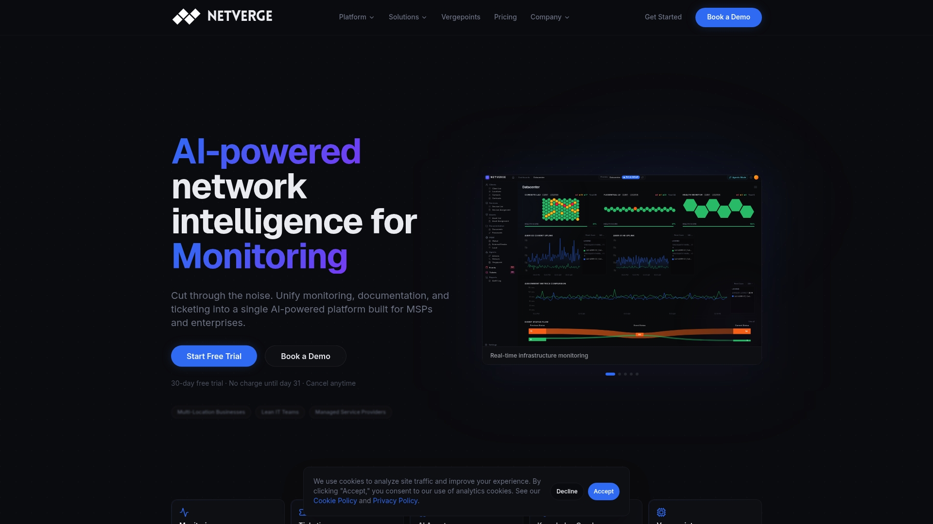
The Starter Package runs $299 per month, with Hardware Vergepoints available at $49 per month per device for teams that need physical visibility at additional sites. If you're planning a sensor rollout and want to see how consolidated telemetry and AI triage fit your architecture, start a free trial and connect your first observation points today.
FAQ
Where is the best place to put a network sensor?
The best placement is at traffic-convergence points, such as core aggregation uplinks, data center east-west links, and internet gateways, rather than wherever a switch port happens to be free. CISA's eVRF framework treats these convergence points as architectural observation points chosen for the visibility they provide, not for installation convenience.
What is a network sensor?
A network sensor is a hardware or software device that captures or samples network traffic at an observation point to feed monitoring, detection, or analysis tools. Sensors range from passive TAPs that simply split a signal to active software agents that parse and forward flow or packet data for deeper inspection.
Where should sensors go for the most complete coverage with the fewest devices?
Research on sensor-placement optimization shows that a small number of well-chosen monitors can cover a large share of network flows when positioned using greedy heuristics applied to a traffic map, rather than placing a sensor on every link. Core aggregation points, combined with one sensor per major site and key cloud egress points, typically deliver the strongest coverage-to-sensor ratio.
Where can you place a sensor in an OT or industrial network?
OT sensors should be deployed passively, never inline, and placed to observe the process network without touching safety or control loops. DOE guidance on ICS and OT monitoring recommends sensors compatible with industrial protocols and ruggedized hardware suited to plant-floor conditions.
Should I use a TAP or a SPAN port for sensor placement?
Use a TAP for security-critical or high-utilization links, since TAPs capture traffic passively without consuming switch resources or risking dropped packets under load. SPAN ports are a reasonable fallback for low-utilization segments or short-term troubleshooting, but they compete with the switch's own CPU and can drop packets during peak traffic.
Sources
- Extensible Visibility Reference Framework (eVRF) Program Guidebook
- Considerations for ICS/OT Cybersecurity Monitoring Technologies | Department of Energy
- CIS Passive Network Sensor Placement
- Towards Optimal Sensor Placement for Cybersecurity - PMC